Airsoft Motor Grips That Can Fit Fat Wires
Airsoft Motor Grips That Can Fit Fat Wires
-
-
The commencement step to re-assembling the gearbox is to brand certain the wiring is in the right place. Check the switch itself is in position and screwed downward.
-
If the AEG is wired to the rear and so it should look like information technology does in the first picture.
-
Check to see if the switch leap is attached to the mail service on the gearbox and the trigger plunger.
-
Brand sure the red wire going across the area circled is on the lesser.
-
Now you can add the trigger make sure the spring that fits on the trigger is attached. Without that bound the trigger will not be able to reset afterwards a shot on semi-auto.
-
-
-
Now the gears can be placed in the gearbox.
-
In one case again try non to lose the shim placement on the gears.
-
The start gear to identify back in the gearbox is the spur gear (the large circular gear)
-
Next comes the Sector gear which has a half set of teeth and place information technology with the post shown in the two O'clock position
-
Next catch the anti-reversal latch and jump and fit them together with the loop of the spring going on the long mail service and hook section on on arm part. Then place them in the hole shown.
-
Keep The anti-reversal latch poled back so that y'all can place the bevel gear in position. The Bevel Gear is the on with the M&G logo on information technology.
-
Make certain the anti-reversal latch and trigger will non pop out of position by adjusting how the spring pushes confronting the gearbox wall.
-
-
-
Now accept the cylinder set the cylinder head in side if it isn't already. The placement should be such that the 2 parts fit flush with indentations in the gearbox. This washed to check if this is the instance before you put the other parts on the cylinder.
-
At present take the cylinder out so you tin can add together parts to it.
-
Then slide the air-nozzle on to the cylinder caput and slide tappet plate onto the air-nozzle.
-
You tin can now put cylinder and all the parts attached into the gearbox as shown.
-
Now put the piston in the cylinder. Make certain the piston tacks aligned properly with the rails of the gearbox and the teeth of the piston are facing the gears.
-
Finally take the tappet-spring and attach it to the tappet plate hook and the gearbox mail service shown. Without this bound the gun will not be able to load BB's.
-
-
-
Now yous tin can add the leap and spring-guide.
-
Make certain to hold the piston down equally shown wile working further.
-
Now make certain that all of the parts are not out of alignment or fix in a style that would finish the gearbox vanquish from coming together.
-
The most common offenders are the safety latch, the anti-reversal latch, the rear wiring and the piston.
-
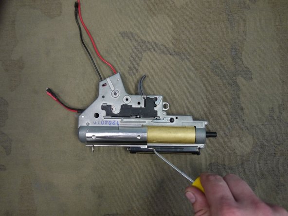
You can at present accept a long sparse screw commuter and slide information technology threw the hallow spring guide to hold downwards the piston and take the other half of the gearbox shell and line it up start with the front of the gearbox and begin pressing information technology in identify.
-
-
-
If y'all somehow managed to become everything aligned perfect great, but 9 times out of ten this will not be the case. If then fallowing volition allow y'all to line up problem parts hopefully without re-opening the gearbox.
-
Apply your small thin tools to re-position problem parts if possible.
-
Starting time with the gearbox held together by hand, check for proper wire and prophylactic-latch placement.
-
So try to make sure you have the spring guide in place. If and then then y'all can go on holding the two haves together.
-
At this bespeak bank check to see if the gear and anti reversal-latch axles are placed in the bearing, if non you can manipulate the position of these parts with a pocket-sized sparse tool. If the anti-reversal latch is besides far out of position you might accept to have the gearbox apart again and retry footstep 3 and 4.
-
If all the parts covered so far await like they are in position but the gearbox is nevertheless slightly cracked open up it is most likely the piston. Luckily at that place is a play tricks to dealing with this. Which will be pace 6.
-
-
-
Wile property the gearbox together take a long driver that fits downward the cylinder head preferably with a apartment lesser ( a 2.5mm hex driver is perfect) and push the piston back. The piston will nigh likely snap right into place.
-
-
-
After that you should have everything in place and can begin adding the screws to the gearbox. The best idea is to start with the center screw and work your manner outward.
-
Once that's done y'all can begin going threw and checking a few parts to be sure everything is done correctly.
-
First cheque the piston past repeating step 6. This done for a few reasons
-
Beginning to make sure the piston is properly in place because that doesn't ever forestall the gearbox from fitting together
-
2d if yous are using a piston from a different manufacturer some make can be manner to fatty and will exist dragging on the sides of the gearbox when moving back and along. This volition cause low velocity and catastrophic failure of both the piston and over time the gears.
-
Now Check the air-nozzle and tappet plate past gently grabbing the air-nozzle past pushing it hands back and letting go. It should spring back into position quickly and smoothly.
-
If it does not function properly do not strength it as this could damage parts. This could be a issue of improper installation or a bad fit if you are using a non-One thousand&G air-nozzle and or tappet plate.
-
-
-
At present that the gearbox is altogether it is now time rebuild the blow-back assemble.
-
So first put the small light-green rubber gasket piece in place as shown. Take the side that is more rounded facing up and flatter side facing down.
-
Now accept the blow dorsum cylinder slice shown in the 2d pic and printing it in identify on top of the gearbox.
-
-
-
With blow back cylinder in position you tin can at present add the blackness cylinder retainer piece. But line it and slide on as shown. It helps to accept a soft mallet if you are having difficulty.
-
Side by side y'all tin add the gearbox servant strap to the rear tiptop section of the gearbox.
-
Have the larger pigsty at the back so you will accept a easier fourth dimension removing information technology for future gearbox maintenance or modification.
-
-
-
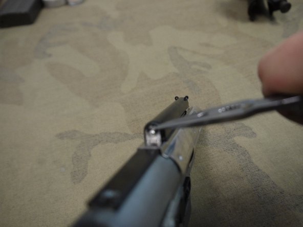
Now careful take the faux bolt and line the two hooking sections with the slightly larger opening on the cylinder servant piece. If they are lined upwards properly y'all should be able to push the hooking sections into the place with a slight snap to them.
-
-
-
You can now slide the fake bolt frontward and fit the hole in the back of the fake bolt over the piston slice.
-
At present you can add a C-clip to secure the false commodities to the piston of the blowback system.
-
Y'all can add the C-clip can exist added past holding it into position and printing into place with pliers
-
-
-
Now y'all can install the selector link slice.
-
Take the side with the long arm and with the axle attached slide information technology in the position shown.
-
On the other side press the gear part on to the linking axle slice and take the gear line upwardly with the selector as shown.
-
-
-
Now before placing the gearbox in the AEG lower body make certain the selector indicator is placed in the gearbox.
-
Set the indicator pointing upwardly give-and-take aka the semi-auto position. Although information technology will most likely move out of place wile placing the gearbox in the lower.
-
Next brand certain the piece that hold the fake bolt dorsum is in the position shown.
-
-
-
Now nosotros can have last become to putting the gearbox back where information technology belongs.
-
First fix the selector to prophylactic and and start positioning the gearbox in the body, Make sure the rear wiring is sticking out the back hole. And the motor wiring is coming out of the lesser area.
-
Equally the gearbox is almost all the way in change the selector to semi to both assist gearbox get into position and allow the selector indicator to friction match the selector itself.
-
If the Indicator does not match the selector button the gearbox slightly out so the indicator piece is not making contact and using your finger turn indicator into the same position equally the selector and so allow the gearbox down once more. This may take a few tries to get it right.
-
In one case the indicator and selector are aligned and the gearbox is set into position set up the gun to prophylactic and see if the indicator fallow selector correctly.
-
-
-
Using a punch and or a soft mallet push the small torso pin into place. Think the textured side goes in final
-
To make it easier you lot can push in the large body pin at the rear beginning simply if you find it difficult to go the small pin lined up correctly try doing it with large pin in the outward position.
-
-
-
At present you can add the pistol grip to the gearbox of the gun.
-
Make sure the wiring is going threw the two medium sized holes. With ruby wire coming out of the front hole and the black wire coming out of the rear hole.
-
Make certain that none of the wiring is caught betwixt the bottom of the gearbox and inner top section of the pistol grip.
-
Now add together the grip screws which are black with wide round head. In that location are merely 2 of them despite having 4 spiral holes. Merely make sure the screws are diagonal to each other similar in first picture and so spiral them down tightly and evenly.
-
Y'all may find it easier to add the screws to the grip before sliding it on the gearbox.
-
Now pucker red wire as shown in the second moving picture then that the wire volition exist coming up from the back of the grip. Forgetting to add this pucker is a really common mistake.
-
-
-
Now the motor can exist added to the pistol grip. Make sure the leap is attacked to the front of the motor.
-
Wait for the positive symbol on the peak of the motor. This represents the positive connector tab right next to information technology and should be facing the front of the gun as shown, when it is placed into the grip.
-
With the wiring tucked in back of grip slide the motor in. If installed correctly the motor should move upward and down smoothing and bounciness when the motor is pushed downward and then released.
-
You can now connect the wiring to the motor first start with the negative/black connector then the positive/red connector. The cherry-red goes with the positive symbol.
-
-
-
At present the motor plate tin can exist added to the end of the pistol grip.
-
Avert pinching wires.
-
With the plate pressed in place take the motor plate screws (which are 2mm hex with cone fashion head) and spiral the plate downwards.
-
It is not a bad idea to spiral both screw a little loose at first and then finish tightening them afterward both are in place.
-
-
-
Now yous can add the rear wiring and test bike the gearbox to see if you did everything correctly.
-
If that is the case you tin can add the magazine take hold of.
-
Take the magazine release button and spring. Brainstorm pressing it into the receiver.
-
Have magazine catch piece and put it threw the other side and outset turning information technology counter-clockwise to thread the ii pieces together.
-
-
-
Magazine catch in place add together the bolt grab.
-
It connects to a little arm that can be seen behind the gearbox and is held in to the body by a very modest pivot with a little retentiveness O-ring on information technology.
-
But find that pin and push information technology into identify when the dial is pointing.
-
-
-
Now you can add together the sling adapter and buffer-tube to the back of the AEG.
-
Start with the sling adapter. The protruding section go into the AEG and the wiring goes threw the middle.
-
Then with the wiring going threw the in slide the buffer-tube on to the back folio of the body.
-
Then take hold of the big bolt with the washer piece attached and slide them into the back of the buffer-tube with the wring gear up underneath. In one case the bolt is as far as it will get showtime screwing down the commodities using a long Philips spiral driver.
-
-
-
At present y'all tin can add together the charging handle and leap to the top of the gear box.
-
Take the hook on the spring shown and attach information technology to the little hoops on the from of the blow-back gather.
-
Then take the hook on the charging handle and attack it to the hoop on the spring. Then prepare the Charging handle in identify so that it can pole dorsum the faux and residual on top of the blow-dorsum get together.
-
-
-
With the hop upwards all the way in the upper receiver you can slide the upper and lower together.
-
Try to proceed the two receivers flush together and brand certain the dust comprehend does not get in the style.
-
-
-
With the hop-upward unit all the way in the upper receiver yous can slide the upper and lower together.
-
Try to keep the 2 receivers affluent together and make sure the grit cover does not get in the way.
-
One time the 2 one-half's are together press in the forward trunk pivot to lock everything in place.
-
-
-
If the rail where removed front. Now is a good time to put them dorsum on.
-
Pole back the delt ring every bit shown.
-
Place the upper runway on start and the lower piece.
-
Final screw down the screw located on the pinnacle to secure everything in place.
-
-
-
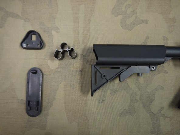
Now without pinching the wires coming out of the back of the buffer-tube slide the stock back on.
-
To do this pull downwardly word on the stock adjustment leaver.
-
Now y'all can add together the remaining stock pieces equally well as your battery and test fire the gun.
-
Have fun!
-


Conclusion
To reassemble your device, follow these instructions in opposite gild.
Embed this guide
Choose a size and copy the code below to embed this guide as a small widget on your site / forum.
Preview
Airsoft Motor Grips That Can Fit Fat Wires
Posted by: vickersnage1948.blogspot.com
0 Response to "Airsoft Motor Grips That Can Fit Fat Wires"
Post a Comment